TESTING
-
ATKORE MARCO HAS FURTHER DEMONSTRATED ITS COMMITMENT TO PRODUCING THE HIGHEST QUALITY PRODUCTS ON THE MARKET BY INVESTING IN A HIGH-TECH SUITE OF SPECIALIST TEST EQUIPMENT
Installation Test Area
Atkore Marco has created an Installation Test Area at their factory premises, where all Marco uPVC Trunking and fittings can be installed and tested in a realistic setting.
Atkore Marco has a spectrophotometer to carry out in-house colour testing, external fire testing (Warrington Fire Testing), in-house quality/testing procedures and supplier test measurements for the uPVC compound Marco purchases.
Thermal Expansion (uPVC)
It is recommended not to run the installation at high temperatures for long periods of time. The table below shows the various temperatures for the different uPVC trunking stages:
| TEMPERATURE RANGE °C | MIN | MAX |
| STORAGE | -5 | +50 |
| INSTALLATION | -5 | +50 |
| OPERATING | -5 | +50 |
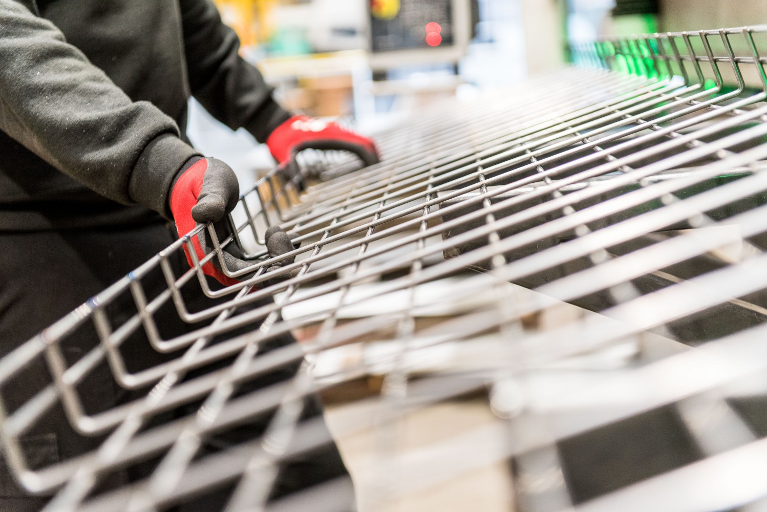
Atkore Marco has further demonstrated its commitment to producing the highest quality products on the market by investing in a high-tech suite of specialist test equipment.
To date, Atkore Marco is the only UK manufacturer of steel wire cable tray to own such high specification in-house testing equipment, which will ensure all products are fully compliant with IEC61537 and related standards. Marco is now able to regularly carry out full deflection tests on all products, and is testing alternative configurations with a view to developing the next generation of trays for the UK and European markets.
Safe Working Load
Atkore Marco steel wire cable trays are tested across two spans and a cantilever. The deflection is measured on the central span using three sensors placed on the sides and at the centre to the tray.
The test method conforms to the BSEN 61537 standard.
Note: The maximum deflection of 1/100 is always reached for a lesser load than that of the safety load. (The breaking point divided by a safety co-efficient of 1.7). CEI/61537
Permissible Load
Permissible loads are tested for a maximum deflection of 1/100th of the span, with a coupling positioned at 1/5th of the span from the support. The coefficient applied to the load for coupling in the middle of the span = 0.7.
Permissible load for maximum sag = L/100 on the intermediate span, coupling at 1/5th of the span.
Recommended Support Spacing
There is an optimum configuration to obtain 2 metre spans without the couplings being positioned at the supports or in the middle of the spans.
To obtain this result, the first span is deliberately limited to 1.5 metres, then the supports are placed approximately every 2 metres. The coupling points are therefore always 0.5 metres from a support.
Supports
The brackets are characterised by their permissible loads (in Kg).
The hangers are characterised by their permissible torques (in Kg.m). All Atkore Marco supports are tested and conform with the standard BSEN61537.
The safe working load (SWL) as defined by the standard is the lowest value of either:
1. The load creating a deflection of L/20 at the end
2. The breaking load divided by 1.7, if the deflection at L/20 is not reached
Electro Magnetic Compatibility
Atkore Marco engage the services of York EMC, part of The University of York, to investigate the shielding effectiveness of Marco steel wire cable tray.
Atkore Marco steel wire cable tray is found to outperform the 200mm pacing configuration required by BS EN50174-2 proven by the independently commissioned EMC tests.
This indicates that Marco steel wire cable tray can offer a more efficient and compact installation (rather than relying on spacing).
Electrical Continuity
Atkore Marco engage the services of York EMC, part of The University of York, to measure the resistance of steel wire cable tray and an MCQC coupler.
The resistance tests are in comparison with requirements EN537:2007 clause 11.1, electrical continuity (1).
An electric current is passed through the system in order to measure the resistance of the coupler. The lower the resistance, the better the electrical continuity.
The maximum steel wire cable tray impedance per metre is set at 5mΩ, while the value recorded using Marco steel wire cable tray is 1.3mΩ, over 3 times more effective than the requirement specified.
Under the requirements of the standard, couplers must have a maximum resistance of 50mΩ. On average, Marco couplers are found to have a resistance of 0.44mΩ, over 100 times more effective than the specified requirement.
The steel wire cable tray and coupler exceed the requirements of the EN 61537:2007 standard for the electrical continuity clause 11.1.
Short Circuit Testing
Atkore Marco has carried out short circuit tests at an independent laboratory in Europe in order to prove that their steel wire cable tray is designed and manufactured with sufficient strength to withstand a short circuit fault.
Marco steel wire cable tray is tested in accordance with the standard that governs the manufacture of cable cleats, IEC 61914:2009 (Cable Cleats for Electrical Installations) in order to prove that the system can be used for installations where there is a fault requirement.
During the test, two lengths of MC106450 (106mm high x 450mm wide) steel wire cable tray are supported and attached at intervals of 1.5 metres to three pieces of strut supports. The steel wire cable trays were coupled together at 1/5th of the span (300mm from the support) using four MCQC (Marco Quick Couplers), on the walls and base of the tray. The cables used to carry the current for the short circuit are placed in a trefoil installation using Ellis Patent’s ‘stainless steel’ Vulcan+ cleats positioned at intervals of 500mm along the length of the tray.
Testing in accordance with the standard IEC 61914:2009 clause 6.4.3, a current of 106KA is applied to the cable. An inspection of the test object then confirms that there had been no damage to either the couplers or the tray with both appearing to have remained in their original state as prior to the tests taking place. In line with clause 6.4.4 another current of 106KA is again passed through the same test object, with an inspection once more confirming that there had been no damage to the system.
The tests confirm that Atkore Marco steel wire cable tray is produced with enough strength and quality to withstand short circuits, enabling the system to be specified on a wide range of electrical installations.
Quick Fit Strut Clip (MCFUSC)
The Atkore Marco Quick Fit Strut Clip (MCFUSC) is ideal for a wide range of installations, including modular builds, as it is able to be fitted prior to transit without the need of additional securing clips.
In order to prove that the MCFUSC can be used in even the most complex of installations, Atkore Marco undertake bespoke testing to the conditions of British Standard BSEN61537.
The testing takes place at Atkore Marco’s in-house facilities, using a Compression and Tensile Testing Load Cell.
To determine a safe working load for the MCFUSC, a test is devised by fitting a length of MC55200EZ (55 x 200mm) steel wire cable tray to a piece of strut, attached using two MCFUSC clips.
The machine is then set to pull away from the centre position up to a maximum force of 80kg, until either the steel wire cable tray deflected 5mm in height, or the MCFUSC failed.
The steel wire cable tray reaches the desired deflection of 5mm with the MCFUSC holding securely in place.
Atkore Marco can therefore prove that the MCFUSC has a safe working load of 80Kg.